So you did your homework, chose carefully, and your shiny new, fresh out of the box inverter has come home. Then the obvious question hits: What now? Welcome to Part 2 of the Off Grid Ham inverter series. We’ll go through some concepts you’ll need to understand to get an inverter safely on line. If you do not yet have an inverter and/or are not sure what to buy, go back and review Part 1.
For starters, a disclaimer: The information given in this article is for general reference, information, and education and does not necessarily apply to every inverter, nor does it apply to any device in particular. If any statements in this article conflict with the manufacturer’s instructions that came with your inverter, then defer to the instructions. Do not attempt any tasks related to installing any electrical device unless and until you fully understand the procedure and are comfortable doing the work involved. Always follow safety rules.
The process of installing an inverter is not that complicated, but there are many ways to mess things up so it’s important to make sure each step is complete and correct before moving on.
Choose a mounting location.
Think about where the inverter will be in relation to the batteries, as well as how you will access the 120 VAC output. Flooded cell batteries give off a toxic hydrogen gas that presents two big problems: The gas is highly explosive, and with long term exposure it will corrode electronics. The dilemma is that you want the wiring from the batteries to the inverter to be as short as possible. Pick an indoor location with good ventilation.
Most inverters have a cooling fan. If mounted vertically with the fan facing down, the cooling is less effective because the fan will be fighting against the warm air that naturally wants to rise up. If the fan faces up, it is working with the convection of the warm air, but the opening in the top will be an easy entrance point for dust and dirt. The best compromise is to mount your inverter horizontally with the fan facing sideways. Do not mount it vertically unless the instructions specifically state it is ok to do this. Even then, I would situate it horizontally anyway for the reasons we just went over.
Tools and materials.
After you have decided where your inverter will be, gather your wire, mounting hardware, connectors, fuses, etc., as well as your tools. At the very minimum you will need heavy gauge wire, a fuse, and a fuse holder. Use a fuse or breaker intended for DC current only. Standard AC fuses/breakers are not acceptable, nor is relying solely on the overload automatic shut down feature.
There are many on line sources for specialty DC circuit protection devices. Unfortunately, they are all expensive. In one of my installations I used a generic fuse block I bought at an auto parts store for only a few dollars. If you are new to self reliant energy, you will quickly learn that inexpensive automotive electrical components can be easily adapted for off grid power needs. No matter what, make sure you have appropriate overload protection.
Sorting out wire gauges.
For safety and efficiency reasons, it’s really important to use the correct wire size. In some cases the wire needed to run at maximum power is either very expensive or available by special order only. The larger gauge wire is also very difficult to work with and may require special tools. Manufacturer specifications for wiring assumes you will be running your inverter at full power, all the time. In the real world, that hardly ever happens.
If the inverter manual specifies wire larger than you are able to handle or obtain, there is a safe workaround but it comes with a tradeoff.
The workaround is to use smaller wire, and the tradeoff is a lower power output capacity. For example, say you have a 600 watt inverter, but the wire you want to use will only handle 300 watts. Use the smaller wire anyway, and this is really important, make sure your fuse is sized appropriately for the capacity of the wire. The setup will be safe, but you will never be able to pull more than 300 watts out of your 600 watt inverter.
Another example: My 1100 watt inverter is connected with a less than ten feet of 6 gauge wire through a 50 amp DC breaker. Technically, this arrangement will not safely handle 1100 watts. However, I’m willing to give up a few hundred watts for the convenience of using the smaller wire (my batteries are not beefy enough to provide 1100 watts of long term juice anyway). I can use my setup with high level of confidence that it is completely safe.
This on line calculator from Blue Sea is a great tool for computing exactly how big a wire gauge is needed for any given amount of current. It also takes into account the length of the wire.
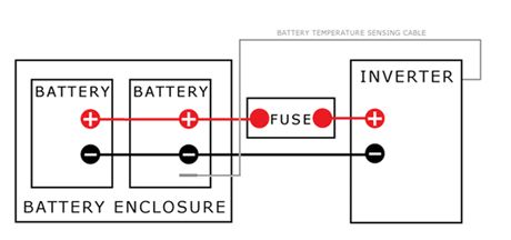
It’s worth repeating: You absolutely must have a fuse on the positive battery lead as close to the battery as possible. The fuse should be rated for the capacity of the wire, not the capacity of the inverter. Yes, this is a very big deal.
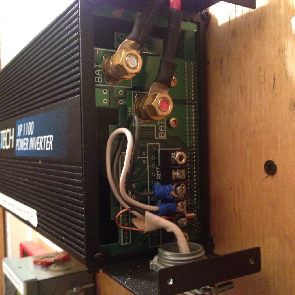
Run your wires from the inverter to the battery, making sure the terminations are tight, clean, and neat. Do not make any connections on the battery yet. The fuse or breaker should be on the positive lead as close to the battery as possible. Photo 1 below is the battery connections and AC output on my inverter. Notice that the battery leads are custom cut to size and neatly dressed with shrink tube. I am proud to have my name on this and every job I do. Approach your off grid projects with the same attitude; care about what others may think of your work.

PHOTO 1, INVERTER CONNECTIONS. BLACK/WHITE WIRES RUN THROUGH A BREAKER BOX TO OUTLETS AROUND THE HOUSE. ORIGINAL PHOTO ©2016 OFF GRID HAMI
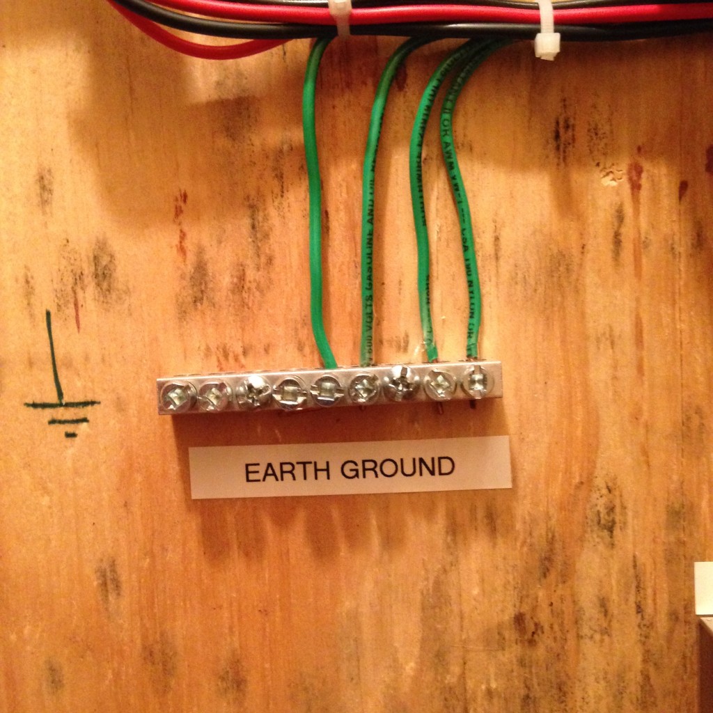
If your inverter has a ground lug, run a wire from the lug to a solid earth ground. Failure to do this may introduce noise/interference into your equipment; it will also disconnect the third prong (ground) lead on your inverter AC outlets and defeat an important safety feature. If your model did not come with a ground lug, do not add one on your own or make any alterations.
With the inverter power switch off, verify that the wire and fuse are the correct size and the connections are secure. Connect the positive lead to the battery and make sure it is tight, clean, and neat. Then do the same for the negative lead.
When working with batteries, especially large capacity batteries, the negative lead should always be connected last and disconnected first. The reason for this is if for some reason the positive side of the battery makes unintentional contact with a negative common ground, it will not create an unsafe short circuit condition.
Give everything one last check over. When all is clear, turn the inverter on. It may briefly beep or make high pitched whine sound. The fan may or may not turn on. You may now plug into the AC outlets and start using your inverter.
Connecting an inverter to a grid tied electrical panel.
You cannot wire an inverter to a live commercial power panel unless the inverter is specifically designed for “grid tie” service. Any attempt to integrate an off grid inverter into an energized grid powered panel or system is extremely dangerous. The probability of something really bad happening is 100%. There are no workarounds or safe shortcuts. The peril of doing this cannot be overstated.
It’s worth repeating: You cannot, should not, will not, never, no exceptions, attempt to connect a standard off-grid inverter to any part of a grid powered system. Do. Not. Do. This. Ever.
Creating an independent “micro grid”.
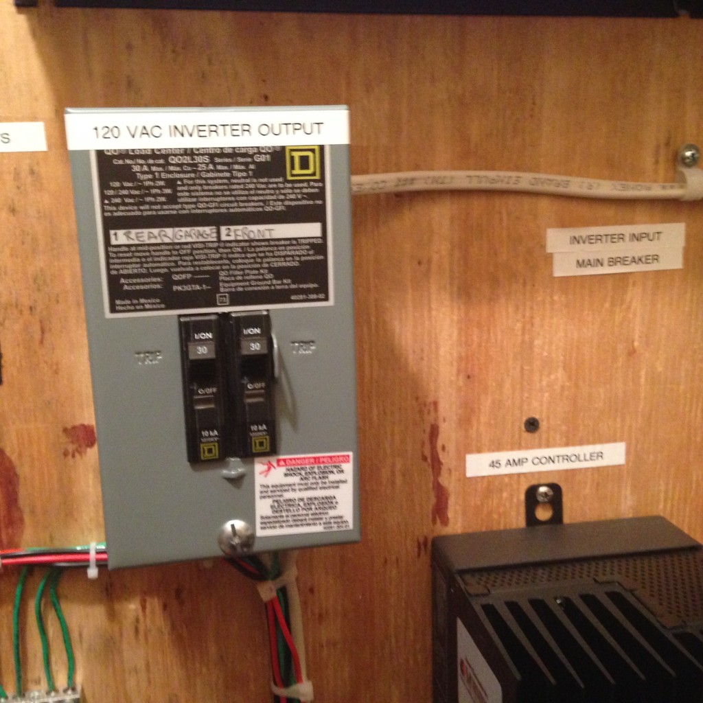
Some inverters have a separate AC output that offers flexibility to extend power beyond what can be done with extension cords plugged into the integrated outlets. On my inverter, I fed this output to a small breaker panel, and from there I wired outlets around my house.
This “micro grid” makes my inverter much more useful as I do not have to run extension cords all over the place. In photo 1 above, the white and black wires are the feed to my micro grid. The inverter based breaker panel, wiring, and outlets are completely separate from and have no physical connection to any part of my grid based electrical system, so I am not violating my own rule about not connecting an inverter to commercial power. The built in outlets will still work normally.
If your inverter does not have a separate AC output (other than the built in outlets) and/or does not have a ground lug, then you must run your equipment directly from the inverter. In general, you cannot use the built in outlets to power a micro grid. Although there is a safe way to do this, I won’t give instructions here because it’s not officially recommended by any manufacturer and I don’t want to be responsible for anyone zapping themselves or others, or burning their house down. If you need to search the internet for how to extend inverter outlets with hard wiring, then you probably should not be doing it.

BREAKER BOX FOR MICROGRID. THE MICRO GRID IS NOT CONNECTED TO ANY PART OF THE COMMERCIAL POWER SYSTEM. ORIGINAL PHOTO ©2016 OFF GRID HAM.
Once the inverter install is complete, check it after a few minutes of use to verify there are no warm wires, burning odors, or other red flags.
What You Need To Know–Key Concepts.
- Do not mount an inverter vertically unless the manufacturer manual explicitly approves of the arrangement.
- The wire between the battery and the inverter should be as short as possible and sized for the expected load.
- Always use a fuse or breaker rated appropriately for the capacity of the wire, not the capacity of the inverter.
- Locate the fuse or breaker on the positive lead as close to the battery as possible.
- Do not rely only on the inverter automatic overload shut down.
- The negative lead should always be connected at the battery last and disconnected first.
- Never, ever connect an off grid inverter to an electrical panel or any circuit fed by the commercial grid.
- The use of a “micro grid” ie, AC outlets hard wired to the inverter but not connected in any way to the commercial power grid, is acceptable.
Setting up an inverter does not require a great deal of skill, but it does require a great deal of care to assure everything will be safe as well as functional. Go slowly and methodically, checking your work along the way. You will be very happy with the end result.


If you need more than 200 W of AC power or so: Why not switch to 24 V DC?
At least here in Europe trucks have a 24 V power system. Therefore it is not so difficult to get a 24 V inverter. At that power level you might have two solar panels and two batteries anyway. Use them in series instead of parallel.
What do you gain? You have only half of the currents. And a certain voltage drop on a cable will hurt your over all efficiency much less.
BTW: The dimensioning of the leads may follow one of two schemes:
* Make them no thicker than they must be to carry the current. You accept that they get warm from time to time. This is the minimum dimension. This might determine the fuse to use.
* Make them as thick as is mechanically feasible. If you end up with thicker wires than above you might improve efficiency. But it might be cheaper to invest in another battery or a bigger solar panel.
I see one advantage of a 12 V system compared to a 24 V system: If one of two 12 V units gets inoperable, you can simply remove it in a 12 V system. If you use sealed lead-acid batteries this disadvantage might not be that bad: Certain models are used very often and therefore they are relatively cheap and easy to obtain. An example is the 12 V / 7 Ah size. So use four of them instead of two.
Hi Alexander, Implementing a 24 volt system as you describe is of course technically possible. However, in the USA where I am based, most everyone uses 12 volts DC. Going with 24 volts presents interoperability problems. For example, if my system breaks down I can more easily borrow parts, or lend parts to others if they break down. A 24 VDC battery would need a 24 volt solar charge controller, which means an expensive MPPT version or very, very, limited choices of 24 volt PWM models. As far your observations about what size wire to use, I would never advise anyone to deliberately under-engineer their system or dismiss warm wires as an acceptable condition. If needed, bump up the voltage (to reduce current), or use larger or shorter wire…do whatever is needed to operate within a margin of safety. Thanks for your contribution to Off Grid Ham. I hope you’ll come back again and tell all your friends.
Hello Chris,
I would not stress these interoperability problems: Nothing prevents you from using two solar panels with their separate charge controllers. You would only have to monitor the minimum voltages of your batteries separately. A 24 V system with a 12 V inverter has another advantage: The inverter can provide 13.8 V regardless what your batteries provide.
Another idea that I have used successfully for years with my mobile station: From the car hifi people you can get “power caps” that have a capacity of one to several Farad (no nF or µF!). The mean supply current of my Yaesu FT-857D with 100 W of SSB output is less than 5 A. This way I can easily operate it from the 12 V outlet in the trunk of my car – and get compliments for my modulation quality – see http://www.dl4no.de/thema/mobil-st.htm. If you think this through such a power cap eases quite some restrictions.
About telling my friends: see http://www.dl4no.de/thema/hamradio_shortwave_links.htm#blogs
One of the great things about ham radio is that there are so many ways to approach a situation. I love the idea of using a large value capacitor in your mobile rig. Since a capacitor is just a glorified battery anyway, the concept makes perfect sense.
Also, thank you so much for linking Off Grid Ham on your website. I’m really grateful for the support and will add a link back to you from here soon.
Thanks again & 73.
Assuming the proper wire gauge cannot be used, is there anything that counter-indicates the use o 2 -or 3- lengths of suitable smaller gauge wire?
Technically two or three smaller gauges combined should equal one single large gauge. However, it is considered highly unprofessional and not allowed by any electrical code, at least not in the USA. There is not even a formula I am aware of that will do the conversion. It’s just not a good idea.
Personally, I would not do it unless it was a survival situation and there was no other alternative.
Please consider what happens if one of your wires comes lose!
This is why ALL mobile rig power cables come with fuses in both the positive and negative wire: If the main ground connection of the battery loses contact all battery currents would run through the rig’s wiring to the antenna mount or other ground connection.
Nothing stopping you from individually fusing each cable to it’s rated ampacity. I don’t know about elsewhere but here in Canada multiple parallel equal sized conductors are commonly used in electrical installations. The ends are all terminated in the same connector, so one coming loose means all of them coming loose. This is without individual fusing of each conductor, doing so could only make it safer as far as I can see.
If I was really paranoid I’d run them all inside a metal conduit.
Hi Dustin, your idea will technically work, but if a fuse in one wire blows, it will create a cascade effect on the other conductors. Keep a lot of spare fuses around!